Qanis - A Quadruped Robot
For a university project, we decided to build our own quadruped robot, inspired by well-known models like 'Boston Dynamics' Spot.
Lucca Bauer, Matthis Bauer, Jonas Fischer
25-07-23
Introduction
Project Overview and Objectives
For a university project, we decided to build our own quadruped robot, inspired by well-known models like Boston Dynamics’ Spot. In previous semesters, we had developed plenty of web applications, so this time we were looking for a new challenge and were especially interested in working on a hardware project. After some online research, we settled on building a quadruped robot. It seemed like a difficult task, but one we could realistically take on within a single three-month semester. The project name, Qanis, is a combination of quadruped (four-legged) and canis (Latin for dog).
Design Constraints and Specifications
Given our time constraints, we set a few realistic goals. The main one was to design both the hardware and software entirely on our own. For our minimum viable product (MVP), the objective was for the robot to stand up and balance itself. By the final submission, we wanted Qanis to be able to walk.
Since we were funding everything ourselves, we worked with a limited budget and aimed to keep costs low. That said, we still had to make some key purchases, such as a 3D printer from Bambu Lab and 12 Dynamixel servo motors. Our choice of materials was mostly restricted to basic 3D printing filament, which introduced some challenges later on and eventually led us to incorporate a few non-printed parts – more on that later!
In terms of size and weight, we aimed for a small form factor that still looked like a real robot, not a toy. This goal brought its own set of challenges, ultimately requiring a complete redesign.
Current status
At this stage, following the end-of-semester submission, the robot can perform several predefined movements such as sitting, lying down, standing up, and wagging its tail. During the end-of-semester presentation, people were most impressed by its ability to balance itself while the ground beneath it was moving. Currently, Qanis is able to walk, though the motion is not yet very smooth. The project is still a work in progress, and we are highly motivated to keep improving and developing it further.
Mechanical Design
Leg Design
When we started, we had no idea what our robot would look like. It seemed logical to begin with the leg design, as it’s the most fundamental part of the robot.
The leg design went through multiple iterations (Fig. 1). The first version was a quick design just to get something up and running. This allowed us to parallelize our work, as some of us could start familiarizing ourselves with the Dynamixel AX-12+ motor interfaces and begin working on the software right away.
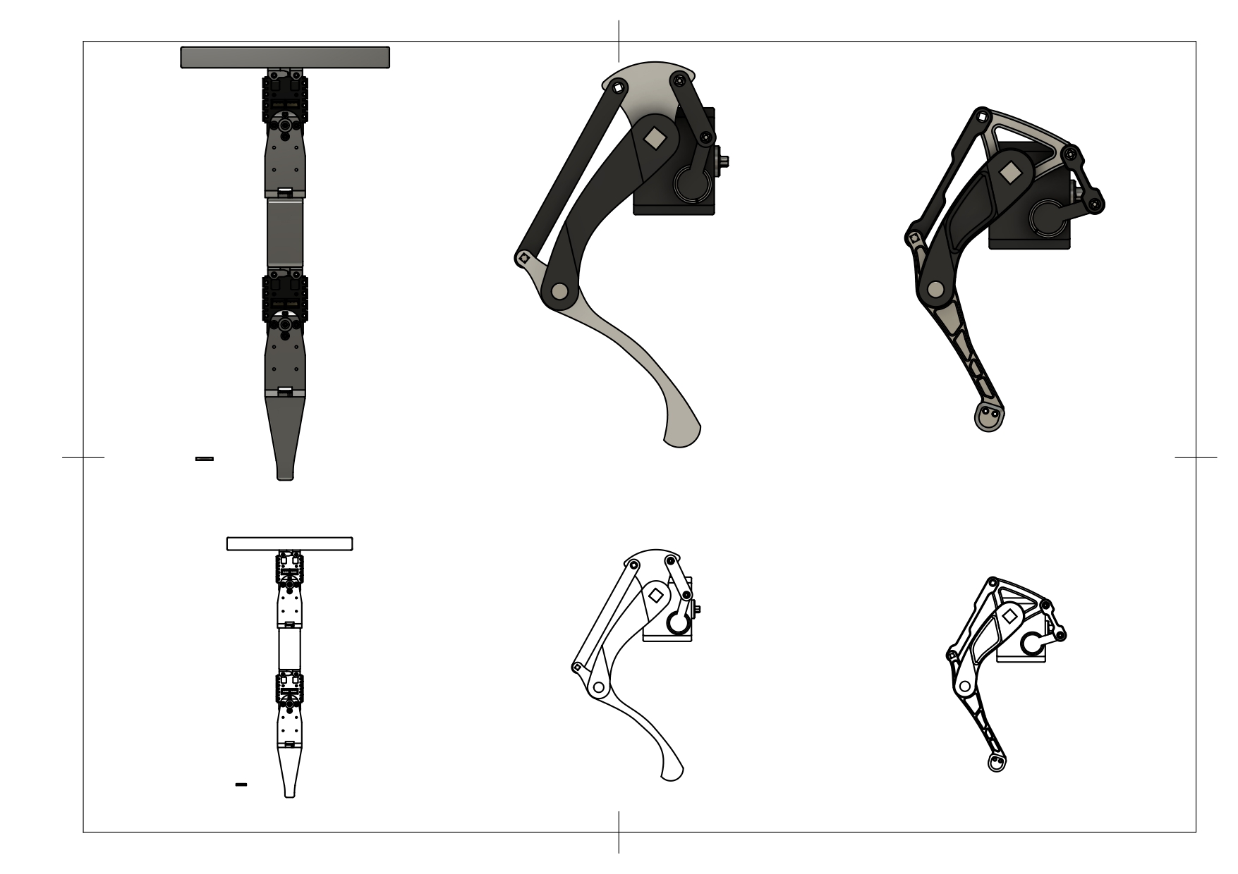
Fig. 1: Leg iterations
We put a lot more thought into the second design. We created a motor box to hold two motors: one to drive the upper leg directly and another to drive the lower leg via a four-bar linkage system. We saw this linkage system in many other designs, and it’s very useful for reducing torque on the motors by keeping the weight closer to the body. The plan was to attach this entire motor box to a third motor, allowing the leg to rotate in y axis.
However, with this second leg design, we hit a major roadblock: the robot couldn’t even lift itself off the ground. At first, we had the feeling that we bought motors that just weren’t strong enough which was really frustrating. After reconsidering our design and doing more research, we found the real problem. Our linkage system had “dead angles” - positions where the links were at nearly 0 or 180 degrees. In these positions, the force transmission drops to almost zero.
For the third iteration, we completely redesigned the lengths of the links and legs to avoid these dead angles. We built a 2D model of the leg in GeoGebra to find the optimal lengths for both standing and sitting positions. This led us to increase the lever size on the lower leg to improve force transmission, making it easier for the robot to stand up. To be extra sure it would work, we also reduced the robot’s overall size, shrinking the legs from 13cm to 10cm.
The redesign was a success! The robot could now get up from the ground with no problems. With the mechanical issues solved, we could finally focus on the software.
CAD Models and Assembly Drawings
All parts of the Qanis model were designed using Fusion 360. Every component was designed individually and linked to the robot in an assembly file. When a component was updated, the updated version got automatically updated as well in the assembly file due to the linkage of the components. This had the major advantage, that we could always see at first sight, if something was able to fit into our model which was especially important during the later iterations where we redesigned the leg components as well as the hull of the robot. Another big advantage of using Fusion 360 was the real-time joint simulation which allowed us to inspect and test all movement ranges.
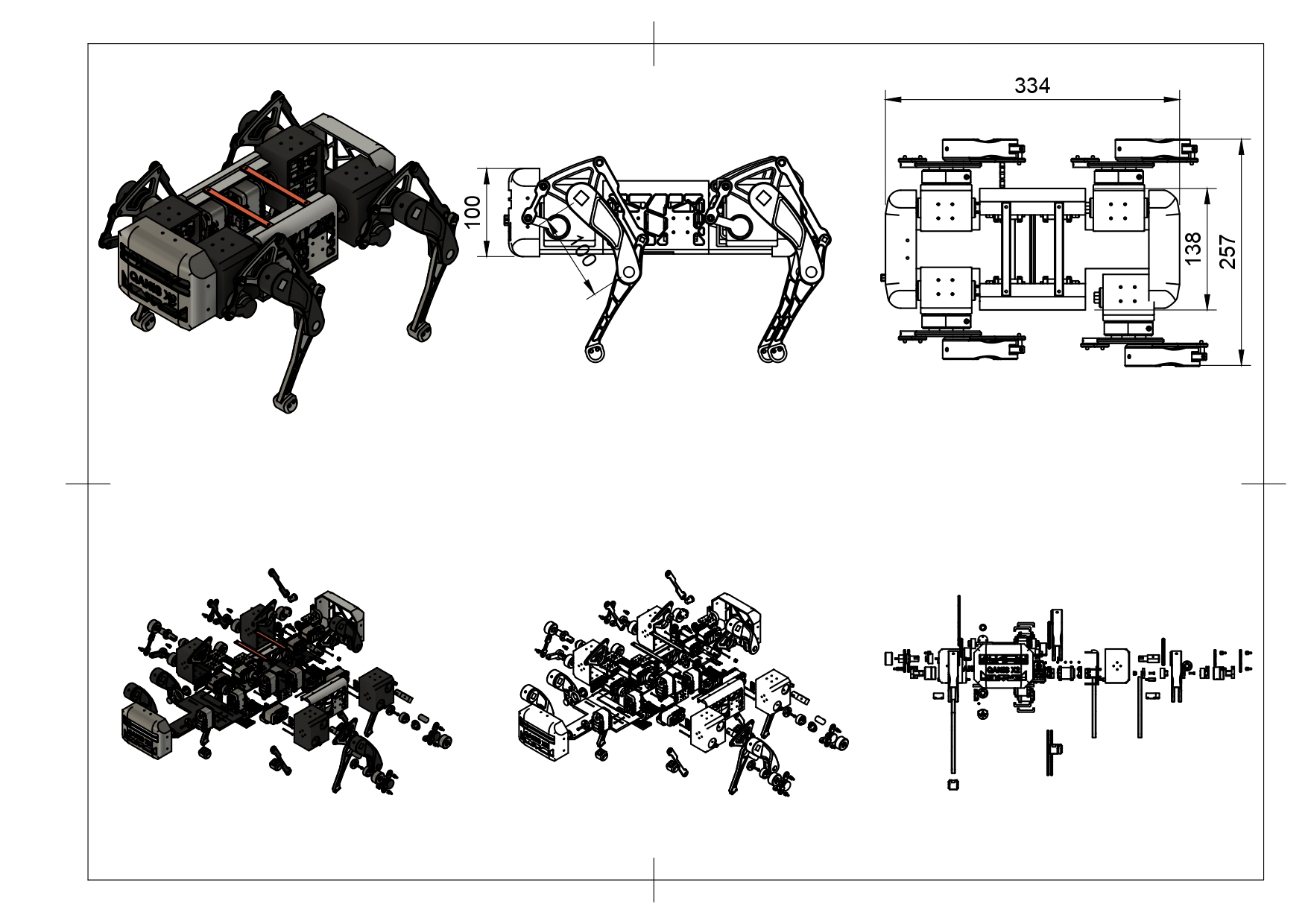
Fig. 2: Robot structure
The robot is made up of 112 individual parts. The main components include the base plate, front and back torso covers, side covers, four legs, four shoulder shafts, four bearing brackets, and two connection struts. At the base of each leg is a motor box, which houses the two motors that power the leg’s movement. The box is mounted to a third motor that controls rotation in the y-direction and is supported on the opposite side by a shoulder component attached to the torso for added stability and reduced stress. Most components are connected using our custom coupling design (Fig. 2). Every moving joint is supported by a bearing to reduce friction. We used two bearing sizes: a larger one (12mm outer, 8mm inner diameter) and a smaller one (8mm outer, 3mm inner diameter). Each leg uses three of the larger bearings and four of the smaller ones for the linkage system.
While the upper leg is directly coupled to its motor, the lower leg is connected via a linkage system that transmits the motion from the motor to the leg (Fig. 2).
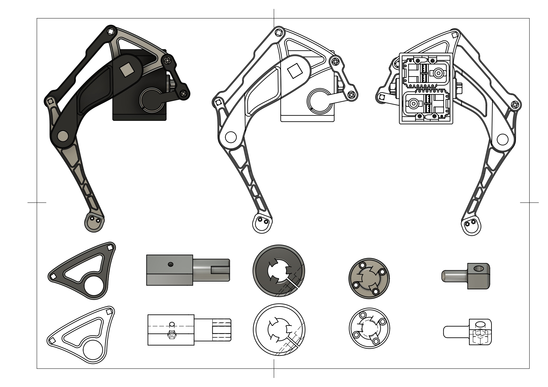
Fig. 3: Leg structure
Material
Our main material was PLA from Bambu Lab. Since we were new to 3D printing, PLA was a great choice because it’s one of the most versatile and forgiving materials. A helpful feature of using Bambu Lab’s filament with their printer is that the printer automatically recognizes the material and color via an NFC tag and pre-configures the optimal settings in the Bambu Studio software.
Initially, we used only 3D-printed parts. However, after assembling our first prototype, we realized that small, printed parts like the coupling shafts for the linkage system couldn’t handle the forces during fast movements. Our first thought was to buy long 3mm stainless steel rods and cut them down, but cutting them cleanly proved difficult. We even headed to the hardware store to buy a special sawing blade just for the task. It was during that process that we realized there was a much simpler solution: using standard 3mm screws and nuts. This worked well, but we later noticed the nuts would loosen over time due to mechanical loads. In the future, we plan to use nylon-insert nuts to prevent this.
Actuator
The motors we used are Dynamixel AX-12+. The servo motors have a stall torque of 1.52kgf/cm with 1024 positions to control in a range of 300°. The motors use a half-duplex communication protocol based on TTL-level UART signaling. One of their biggest advantages is the Dynamixel SDK, which simplifies communication by handling low-level protocol details. This made setup much easier and allowed us to connect the motors in a daisy chain and control them individually using their assigned IDs. A big difference to most servo motors in this price range is that they are able to provide feedback about their position, load, speed and more, making them suitable for a wide range of tasks. In the current state of the project, this feedback is only used for debugging and testing, but there are plans to use the information to improve smoothness of motion.
Electrical Design
Power System Architecture
Currently, Qanis is powered by a stationary power supply, with plans to eventually make it fully battery-operated. Due to the high current draw of the 12 motors, we had to switch power sources several times. In high-load situations – such as standing up from a seated position or when the leg angles result in poor power transmission – the motors can draw up to 18A in total at 12V, which is more than most standard power supplies can handle. This led us to use a laboratory-grade power supply capable of delivering a stable 12V at up to 30A. To manage the load, power is distributed across four separate circuits – one for each leg – to minimize the current passing through our thin jumper cables (mostly 0.5mm).
Microcontroller
The microcontroller needs to handle multiple sensors and perform calculations quickly. With future features in mind, computing demands will only increase. For now, the choice was easy – we had a Raspberry Pi 4B available, and it met all the requirements. Its only potential downsides – power consumption, size, and weight – aren’t an issue at this stage. It’s powered separately, fits easily into the design, and switching to a smaller controller would save no more than 20g, which is negligible compared to the overall weight.
Sensor Integration
Currently, the only sensor in use is an Inertial Measurement Unit (IMU), which provides data about the robot’s orientation and helps keep the body balanced and level. The data is transmitted to the Raspberry Pi via the I2C protocol and processed at a fixed tick rate.
Software Architecture
The software is written in Python and designed to be as modular as possible, allowing us to easily expand or modify individual components. For example, the current gait generation is very basic. Due to time constraints before the end-of-semester presentation, we used a simple pre-generated trajectory that loops continuously. However, we plan to replace this with a more advanced approach, such as using control methods commonly found in professional robotics, like PID controllers. The code is organized into five functional packages, with a dedicated config package that centralizes all variable settings in a single file for easy management.
ROS
We initially planned to use ROS (Robot Operating System), but soon realized other tasks had higher priority. Setting up ROS proved more time-consuming than expected, and since we currently only have one sensor publishing data, the benefits were minimal. However, as we add more sensors and develop more complex features, implementing ROS will become essential – so it’s one of our next planned steps.
Simulation Environment
Early on, we tried using simulation software for the robot, attempting to work with ROS2 and Gazebo, which are commonly used in professional robotics. However, we ran into difficulties creating an accurate model of our robot and converting it into a URDF file compatible with Gazebo. The alternative – remodeling the entire robot from scratch in URDF – would have been very time-consuming. As a result, like with the ROS integration, we had to set simulation aside and focus on more critical tasks. For now.
Control Algorithms
Inverse Kinematics
Inverse kinematics (IK) is a method commonly used in robotics to determine the joint parameters, in our case position of the motors, needed to achieve a desired position of the robot’s foot. Given the desired position of the foot, which we previously generated with our trajectory generator, we calculate the values for the joint’s angles to get there (2D Version: Fig. 4, right side).
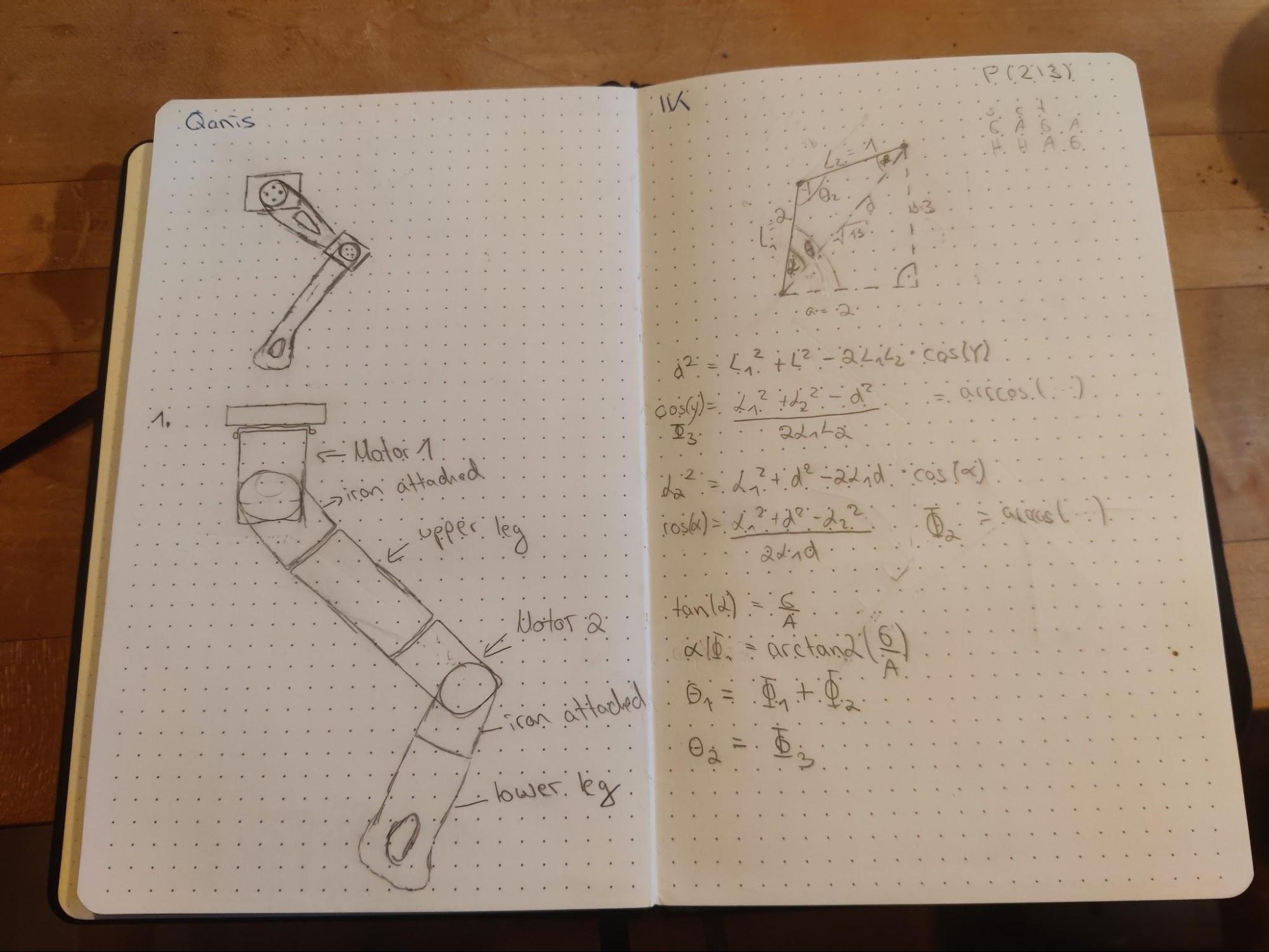
Fig. 4: Early design and inverse kinematics calculations
Once we know the angles of the limbs, we have to do an additional step for the lower leg, because the motor is not connected directly at the rotation point. Instead it is linked by a linkage system to reduce weight and leverage. This means we have to translate the angle we calculated for our lower leg (BAD, Fig. 5) to the correct motor angle (FGD, Fig. 5), which is done by calculating the angles of two 4-bar-linkage systems (ABCD and DEFG separated by a fixed offset, Fig. 5). We used a model of our leg, which we designed in GeoGebra to test and validate our IK and linkage solver.
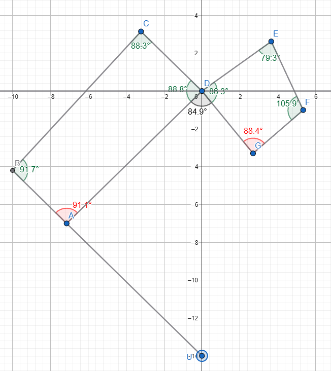
Fig. 5 mathematical model of the robot leg
Gait Generation Algorithms
While researching quadruped locomotion, we learned about the three main gaits: walk, trot, and gallop, each with a different rhythm. To reduce complexity and meet our deadline, we started by implementing a basic walking gait.
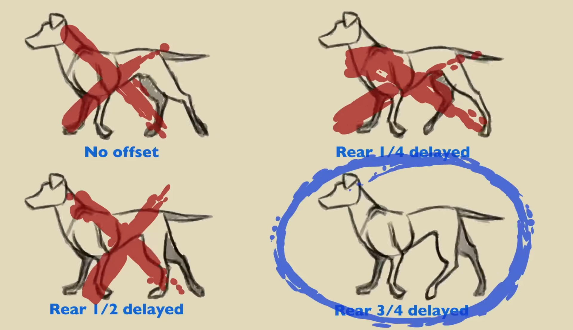
Fig. 6: leg offset of quadruped walking gait
Based on our analysis, a quadruped walk uses a 3/4 delayed rhythm (Fig. 6 and 7) between the front and back legs which we tried to base our implementations on. We then experimented with different timings, foot placements, and torso heights, mostly through trial and error, to see what worked best.
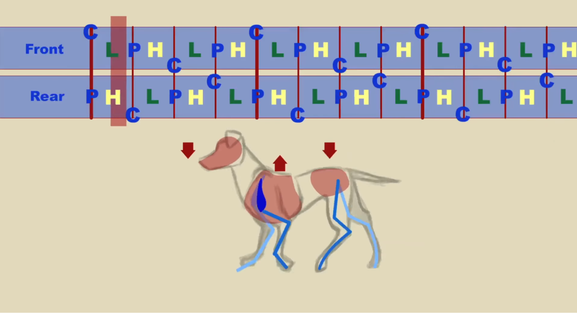
Fig. 7: Breakdown of quadruped walking gait cycle
A stable walking gait relies on keeping the robot’s center of mass within the triangle formed by the feet on the ground (Fig. 8). Currently, our robot’s support triangle is too small, which is why it tends to fall to one side as soon as it lifts a leg. This results in a jagged motion where the robot wobbles forward instead of walking smoothly. In the future, we plan to analyze this more deeply to optimize our walking gait and begin implementing other gaits like trot and gallop.
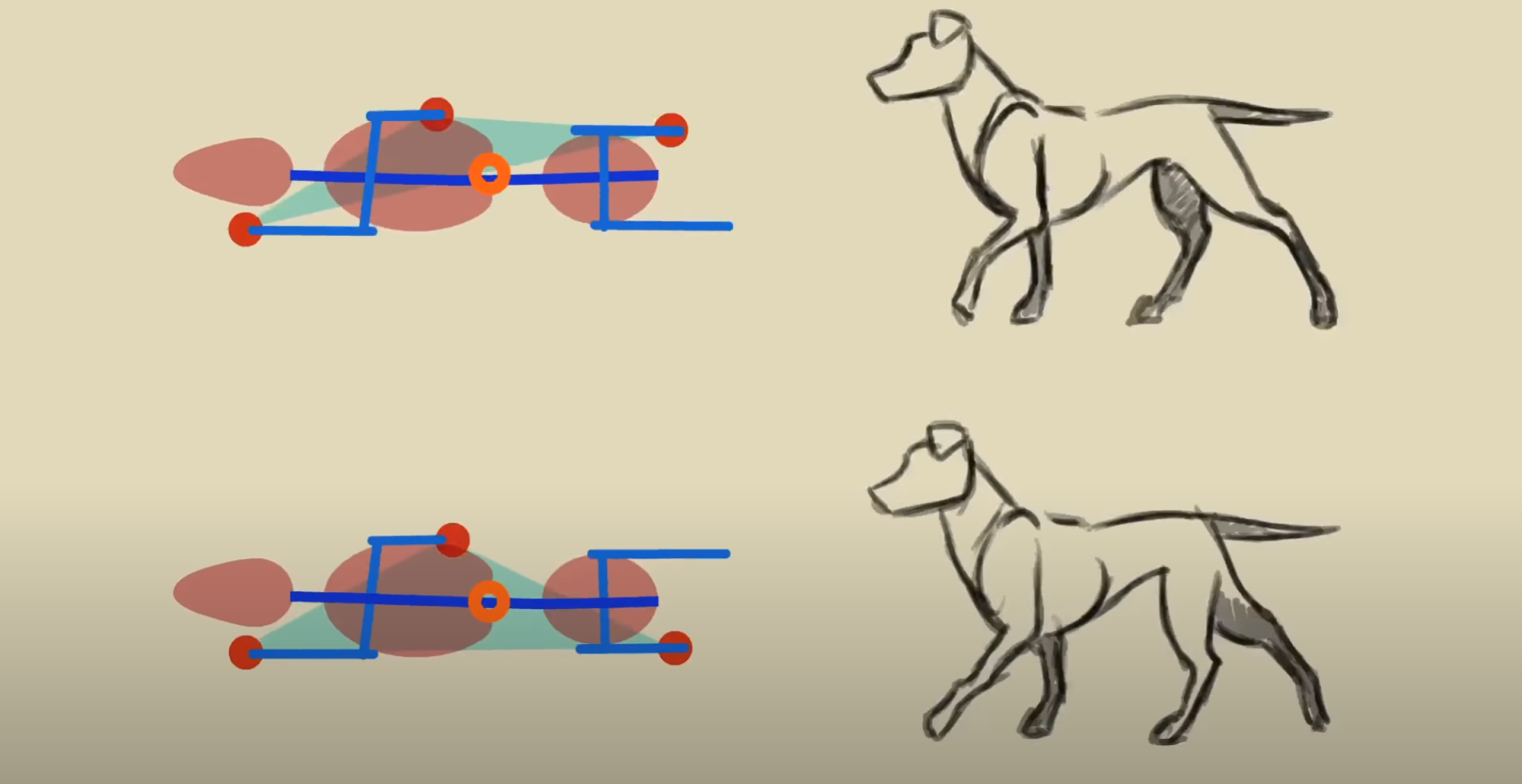
Fig. 8: Center of mass while walking
Trajectory
To implement our walking gait and other pre-programmed motions (e.g. sit and lie down), we needed a way to tell the three motors of each leg to work together to follow a specific path. For this, we are using a trajectory planner. We define a path for the foot’s end-effector and then scatter points along it, which become the target coordinates for our inverse kinematics calculations.
We’re currently facing an issue where the motion is still somewhat jagged and you can see the individual increments as the motors move from point to point. To fix this, we plan to take a step back and focus on getting a single leg to smoothly follow a path, like a square or a circle, at high speed. As soon as the fundamentals are working without any problems and the motor settings are perfect, we will focus on a more advanced trajectory generation.
Results and Discussion
Achieved Objectives
Overall, we are quite happy with the outcome of the project, especially considering we had no prior experience with many of these topics, like 3D printing, electronic circuits, or mechanical design with linkages and inverse kinematics. We managed to achieve all of our initial objectives. While we aren’t fully satisfied with the walking mechanism at this stage, we are confident that with more time, we can improve it significantly.
Limitations and Challenges
During this project, we faced a number of challenges that we had to either solve or work around. The first challenge was finding all the necessary materials and deciding on the methods we would use to design and assemble the robot. Since we had no real prior experience with designing 3D-printed models, we had to start by learning how to use Fusion 360.
The next challenge was figuring out the mathematics behind the inverse kinematics for the foot. We managed to overcome this fairly quickly once we realized that we could use the internal rotation angle to reduce the problem to a 2D case, which we could solve using relatively simple trigonometry.
The biggest problem arose after we developed the first iteration of the robot and realized that it struggled to even stand up. This was a very low point for us—we started questioning the whole project and wondered whether we would even be able to present anything on the final day. After some consideration, we identified three main reasons why the robot couldn’t stand. First, it was too heavy and needed to lose as much weight as possible. Second, the legs had poor force transmission, as mentioned above. Third, the motors weren’t receiving enough current because we were still using a 5A power supply. With the presentation day approaching, we had to solve all these issues quickly. We reduced the weight by decreasing the overall size and using a triangular cut-out structure, since triangles tend to be the most stable shape. We also adjusted the leg dimensions to improve force transmission and managed to find a power supply that could deliver enough current for our needs.
In the end, the last major task was developing the algorithms that would allow the robot to move. We built a software architecture that allowed us to quickly change various settings, so we could manually test which configurations worked best with the current design. Of course, both the mechanical design and the algorithms still need a lot of improvement.
Future Work and Improvements
Our interest in robotics has only grown over the course of this project, and after a short break, we definitely plan to continue developing this robot. Our future plans include:
- Making the robot fully battery-powered so it can move freely
- Adding the ability to control it with a wireless controller, like a PS5 controller
- A major redesign of the kinematics for an improved range of motion
- Focusing on smooth end-effector control, likely by building a single “test leg” to improved trajectory generation and movement execution
- Building a simulation model to train gaits and implement advanced features like footstep prediction
Conclusion
This project was by far the one from which we learned the most. It required us to combine our existing knowledge in software engineering with new skills we acquired during the project. Many of the problems we faced were beyond what we had learned before, so we had to find our own solutions. Our problem-solving skills improved a lot because we couldn’t just follow examples from the internet – our design was unique and needed individual approaches.